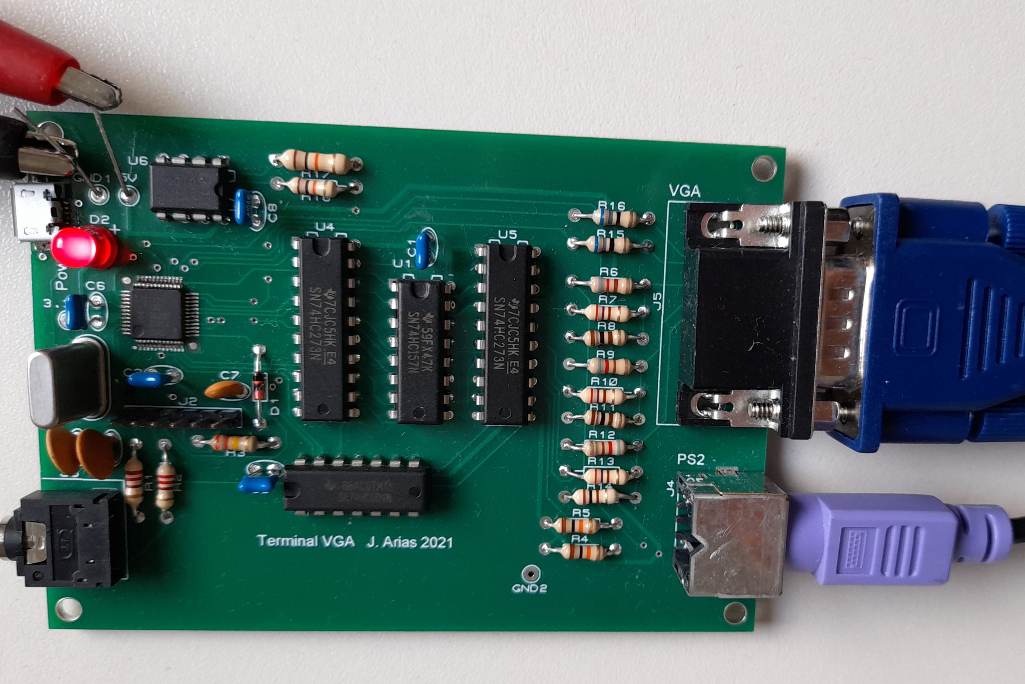

This circuit, when attached to a VGA monitor and a PS2 keyboard, can play the same role as a VT100 terminal. That means: it displays the text received from a serial port and it sends back the ASCII codes of the keys pressed on the keyboard. Its main features are:
The circuit is built around a cheap ARM Cortex-M0 microcontroller (LPC1114 from NXP). Its schematic and layout are:
Hardware details:
The video generation logic relies on three peripherals of the microcontroller: The SSP (Synchronous Serial Peripheral) for pixel timing, A PWM timer for the generation of HSYNC pulses and interrupts, and a general purpose I/O port for the selection of colors. In addition to this some external logic is needed, namely two registers and an 8-to-4 multiplexer. Finally, a resistor-based Digital to Analog Converter is used to translate the 5Volt digital levels into a three-level video signal in the Red, Green, and Blue terminals of the VGA connector.
The SSP is configured for a framed Texas Instruments serial protocol that pulses the FRAME signal every 8 clock cycles. This signal is used to register the color information of each character. The data shifted out of the SSP selects between text and background colors using the multiplexer, and the last register is included because the multiplexer is a combinatory logic circuit that can generate glitches at its output and these glitches would be visible on the screen unless the output is registered (a lesson learned while playing with the Gigatron video)
Video generation also requires a lot of software processing. The HSYNC pulse is generated by a timer along with an interrupt request. The interrupt routine has to feed the color information into the GPIO port and the actual pixels into the shift register of the SSP for each video line. The processor runs at 50MHz and the pixel clock is 25MHz. This means we got exactly 16 cycles to do all the processing of a single character row, and consequently, the related code was written in assembly language. The VSYNC signal is also generated by program in the interrupt routine. Because of this most of the CPU time (73%) is used for video generation and other processing can only take place during the blanking time of the video signal.
If all this complexity wasn't enough, there is still another problem to workaround: The internal flash of the microcontroller uses wait states resulting in a slow and hard to predict execution time. In order to avoid this problem the code of the interrupt routine was placed in RAM, and not only that: the pixel information of the text font also had to be placed in RAM to avoid ruining the timing due to the extra delay of flash reads. This resulted in the almost complete use of the 8kB of RAM of the processor, and some programming quirks were needed in order to to fit in it all the variables (for instance the stack had to be adjusted manually because GCC reserved more space than really needed)
The second SSP controller of the LPC1114 is configured as an 11-bit slave SPI controller for the receiving of keyboard scan codes. Still, it required a pair of quirks: first, the slave SPI needed an slave-select signal that was generated from the keyboard clock by means of D1, R3, and C7. Second, the keyboard sends its data LSB first, but the SPI controller expects it to be MSB first. This was solved by reverting the order of the bits of the received scan code by program.
Finally, an I2C EEPROM memory is included for the non volatile storage of options. The I2C bus communications rely on the integrated controlled of the processor.
Software features:
The processor time not used by video generation is put to good use by the terminal emulation firmware. It includes mainly the translation of the ASCII and UTF-8 codes into the corresponding indexes of the character table, the drawing of a blinking software cursor, and the execution of the control commands. These include some ASCII codes, like carriage return, and all the supported ANSI escape sequences. A list of the control commands follows:
ANSI sequences:
| Low intensity | High intensity | Color |
| 30 | 90 | Black / Grey1 |
| 31 | 91 | Red |
| 32 | 92 | Green |
| 33 | 93 | Yellow |
| 34 | 94 | Blue |
| 35 | 95 | Magenta |
| 36 | 96 | Cyan |
| 37 | 97 | Grey2 / White |
| Low intensity | High intensity | Color |
| 40 | 100 | Black / Grey1 |
| 41 | 101 | Red |
| 42 | 102 | Green |
| 43 | 103 | Yellow |
| 44 | 104 | Blue |
| 45 | 105 | Magenta |
| 46 | 106 | Cyan |
| 47 | 107 | Grey2 / White |
Apart from processing the text and commands received from the serial port, the firmware also translates the scan codes of the keyboard into ASCII codes, UFT-8 / ISO-LATIN-1 codes, or ANSI escape sequences. The only keyboard layout currently supported is Spanish, but that keyboard isn't an easy one. It requires attention to non ASCII characters, like Ñ, and also to accents and dieresis (á, ó, ü...). The numeric keypad is used only for numbers (Num-lock always on), and the edition keys (like arrow-up) are translated into escape sequences (like <esc>[A). The PS2 interface in this circuit is always unidirectional and no commands can be sent back to the keyboard. Therefore the keyboard LEDs cannot be turned on and the Caps-lock state is signaled by changing the shape of the cursor. This last "feature" seems to be a better way of signaling than the LED, as the writer don't have to move the eyes out of the text to see if caps-lock is selected.
Firmware source: Tarball
Some snaps:
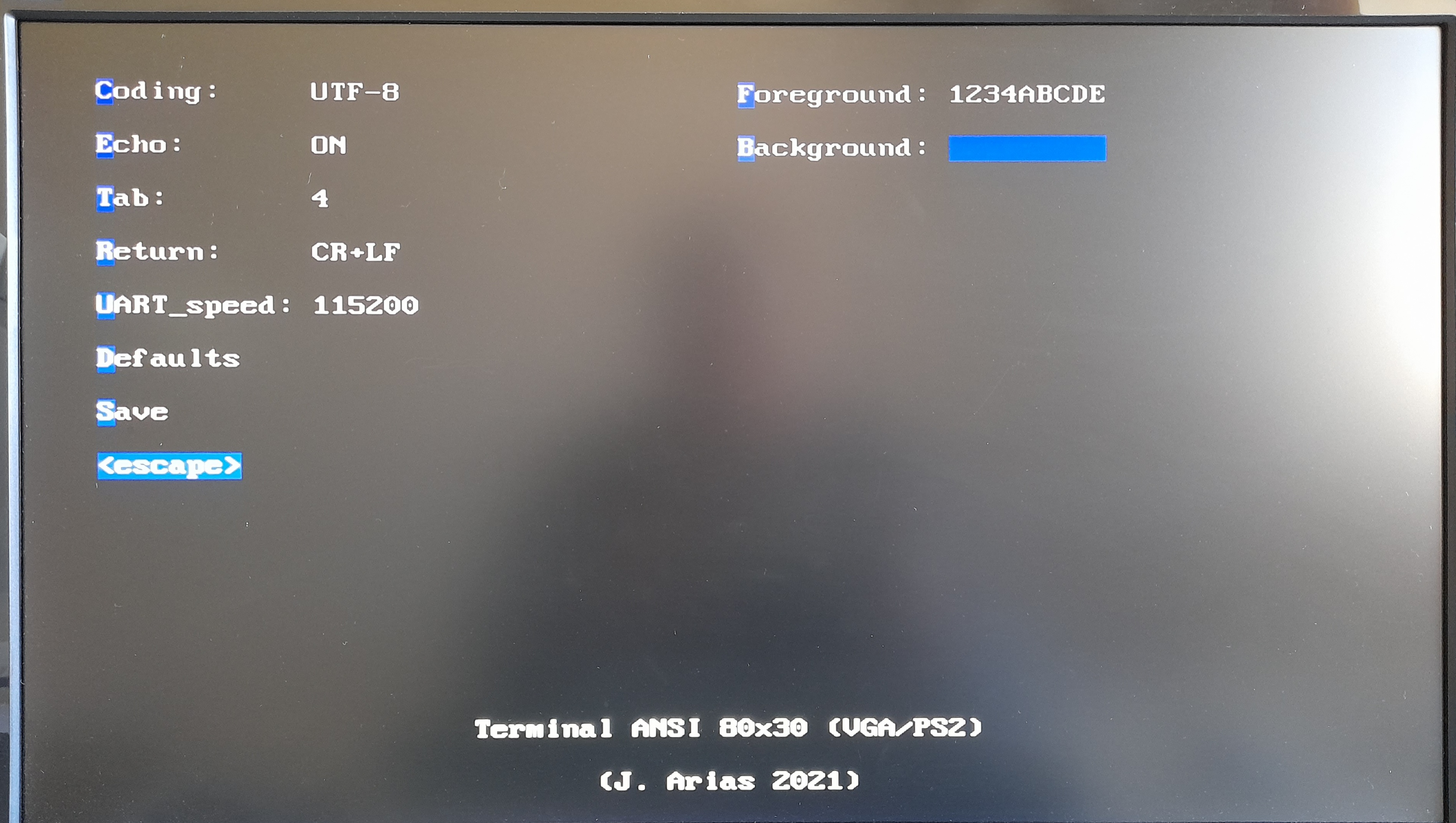
Config screen:

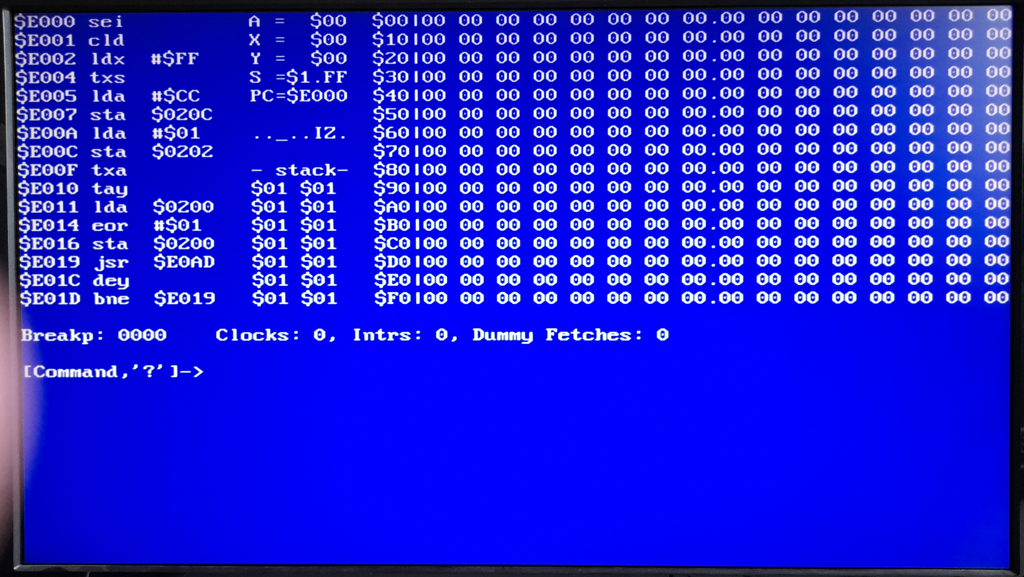
Some text with many cursor positioning codes (cursor was off at the time
of the snapshot):

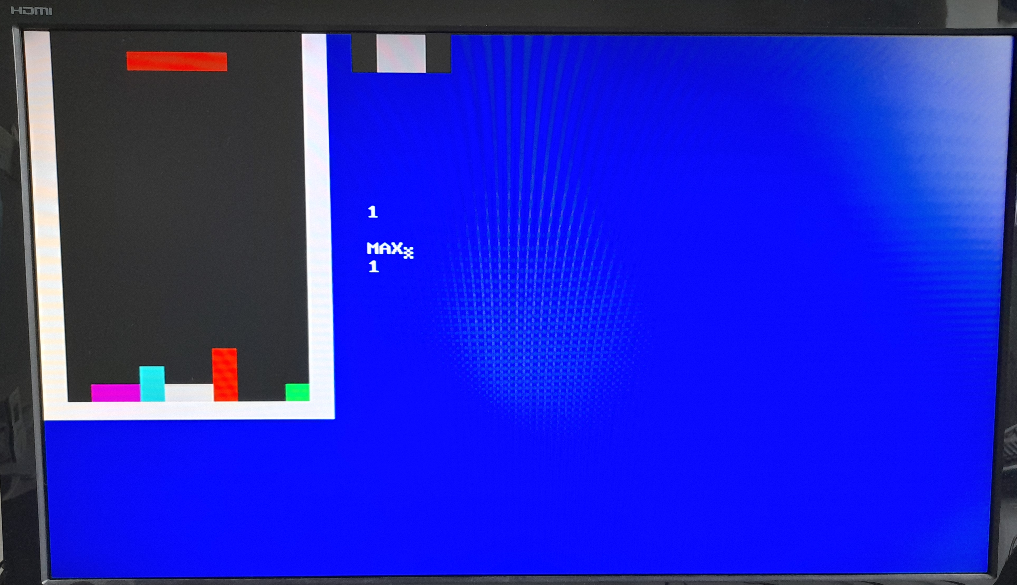
ansitris game, with also lots of reverse video and color
escape codes. Also a lower-case cursor is shown after "MAX" (along with
some unintentional Moiré artifacts...):
