DEFENDER
recreated
(in
a FPGA)
A clone of the vintage game Defender is
designed here. It targets the SIMRETRO board (and now also the
Alhambra-II board):
s
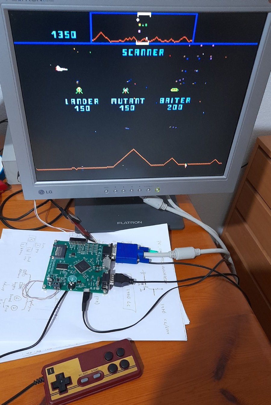
In the above snapshot the SIMRETRO board is
connected to a VGA monitor, an speaker (not shown), a game controller,
and a cell-phone charger used as the power supply (not shown).
The board includes:
- A Lattice ICE40HX4K FPGA with 7680 logic cells (square chip on the
center of the board)
- A 128KB SRAM (rectangular chip on the left of the board)
- An 8MB SPI Flash memory (small 8-pin chip in between and above the
other two)
- A VGA interface (the one plugged to a blue connector)
- A joystick interface (the black DB9) If was designed for passive
Atari-type joysticks, but in this case it was used for a
Nintendo/Famicom game controller.
- A class-D audio amplifier for an 8-ohm speaker.
- A 16MHz crystal oscillator.
- A micro-USB connector for power (connected to a cell phone charger
in the snapshot)
Some details about the design are discussed here:
defrdx.pdf
Documents related to this project:
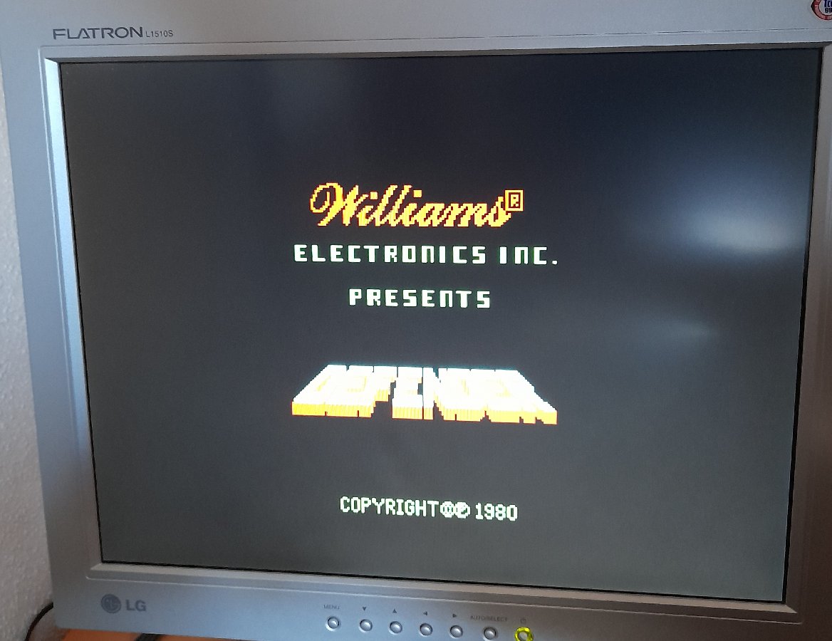
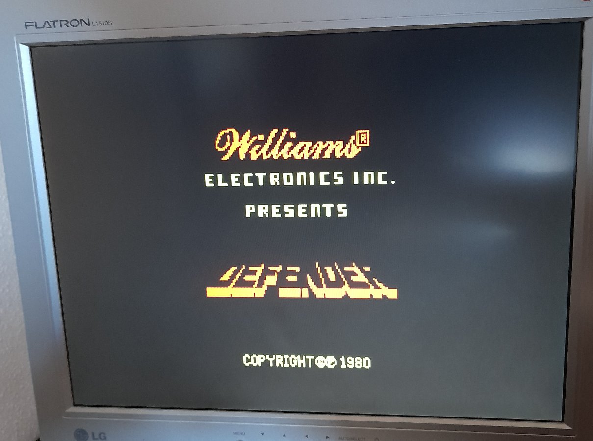
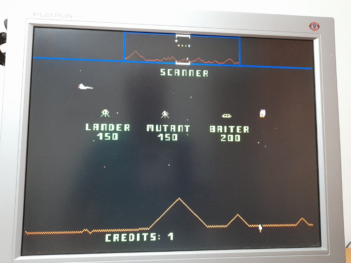
And here are some snapshots:
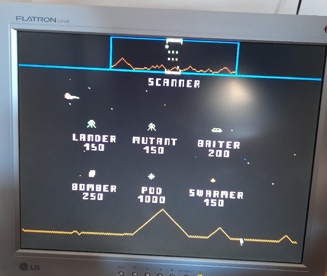
Also, here is a
video of the game. It stars with a reset pulse, then the bootloader loads
the ROM images to memory and also to the screen and, next, the Defender
code starts. First it fills the screen with random data for test, and then
follows the game (sorry for the stupid autofocus):
The original
source code for the SIMRETRO board:
defender.tgz


