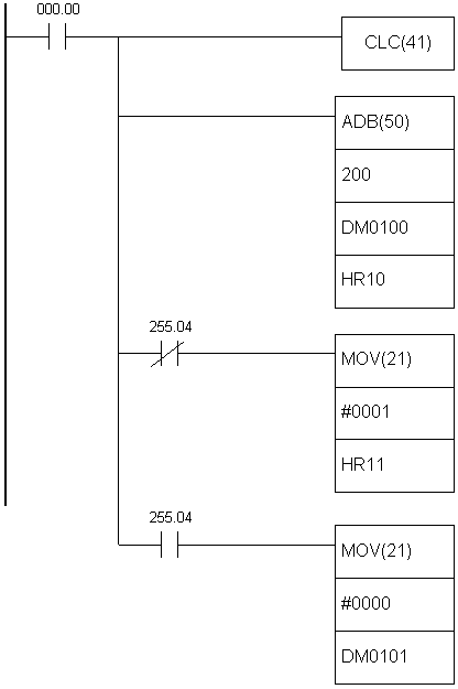
|
APPENDIX
E
Ladder diagram instructions
(3/3)
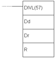
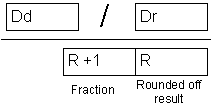
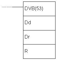
E.51 BCD DIVIDE -
Divides two values
|
Description |
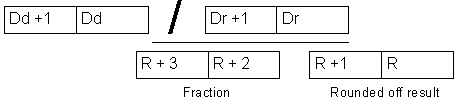
Instruction divides
the contents of location Dd with contents of location Dr. The result
of division is stored in locations R and R+1. The first contains the
rounded off result of division, while R+1 contains the fraction. |
|
Ladder symbol |
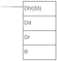 |
|
Limitations |
Words DM6144 - DM6655
cannot be used as operand R. |
|
Flag |
ER flag changes state
to ON if the contents of words Dd and Dr are not BCD.
EQ flag changes state to ON if the result equals “0”. |
|
Example |
Upon fulfilling the condition on bit
IR000.00, instruction divides the value of memory location IR216 by
the value of memory location HR09. The result is stored into two
sequential memory locations DM0017 and DDM0018. The result is stored
so that DM0017 contains round number and DM0018 contains the
fraction. |
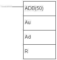
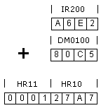
E.52 DOUBLE BCD ADD
- Adds two 32-bit words
|
Description |
Instruction adds
values from addresses Au and Au+1 to values from addresses Ad, Ad+1
and carry bit CY. If the result exceeds 99999999 carry bit CY is
set.
 |
|
Ladder symbol |
 |
|
Limitations |
Word DM6144 - DM6655
cannot be used as operand R. |
|
Flag |
ER flag changes state
to ON if the contents of words Au and Ad are not BCD.
EQ flag changes state to ON if the result equals “0”.
CY flag changes state to ON if there is a carry in the result. |
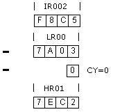
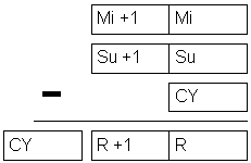
E.53 DOUBLE BCD
SUBTRACT - Subtracts two 32-bit words
|
Description |
Instruction subtracts
the contents of two words Su+1 and Su with carry bit CY added from
the contents of words Mi+1 and Mi. The result is stored into memory
locations R+1 and R. If the result is negative, carry bit CY is set
and 10’complement of the result is stored into R. To get the real
result, contents of R should be subtracted from zero.
 |
|
Ladder symbol |
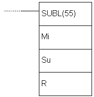 |
|
Limitations |
Words DM6144 - DM6655
cannot be used as operand R. |
|
Flag |
ER flag changes state
to ON if the contents of words Mi, Mi+1, Su, Su+1 are not BCD.
EQ flag changes state to ON if the result equals “0”.
CY flag changes state to ON if the result is negative. |
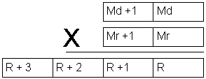
E.54 DOUBLE BCD
MULTIPLY - Multiplies two pairs of words
|
Description |
Instruction multiplies
values of locations Md, Md+1 with the values of locations Mr, Mr+1.
The result is stored into 4 locations: R, R+1, R+2 i R+3.
 |
|
Ladder symbol |
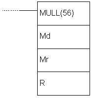 |
|
Limitations |
Words DM6144 - DM6655
cannot be used as operand R. |
|
Flag |
ER flag changes state
to ON if the contents of words Mr, Mr+1, Md and Md+1 are not BCD.
EQ flag changes state to ON if the result equals “0”.
CY flag changes state to ON if there is a carry in the result. |
E.55 DOUBLE BCD
DIVIDE - Divides two pairs of words
|
Description |
Instruction divides
the contents of locations Dd, Dd+1 by the contents of locations Dr i
Dr+1. The result is stored into locations R and R+1 while locations
R+2 and R+3 contain the fraction.
 |
|
Ladder symbol |
 |
|
Limitations |
Words DM6144 - DM6655
cannot be used as operand R. |
|
Flag |
ER flag changes state
to ON in two cases, if the contents of words Dd, Dd+1, Dr and Dr+1
are not BCD or if the contents of locations Dr and Dr+1 equal zero.
EQ flag changes state to ON if the result equals “0”. |
E.56 BINARY ADD
- Binary addition
E.57 BINARY SUBTRACT
- Binary subtraction
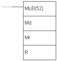
E.58 BINARY MULTIPLY
- Binary multiplication
|
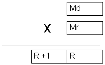
Description |
Instruction multiplies
values of location Md by the value of location Mr. The result is
stored in two memory locations R and R+1.
 |
|
Ladder symbol |
 |
|
Limitations |
Words DM6144 - DM6655
cannot be used as operand R. |
|
Flag |
ER flag changes state
u ON in case of error.
EQ flag changes state u ON if the result equals “0”. |
E.59 BINARY DIVIDE
- Binary division
|
Description |
Instruction divides
the value of location Dd with the value of location Dr. The result
is stored into location R, while the fraction is stored in R+1.
 |
|
Ladder symbol |
 |
|
Limitations |
Words DM6144 - DM6655
cannot be used as operand R and the instruction cannot be used for
dividing signed numbers. |
|
Flag |
ER flag changes state
to ON in case that Dr contains value “0”.
EQ flag changes state to ON if the result equals “0”. |
E.60 BCD TO BINARY
- Converts decimal number to a binary number
|
Description |
Instruction converts
binary representation of decimal number from the word S to binary
number in the word R. Contents of the word S remains unchanged. |
|
Ladder symbol |
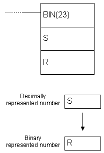 |
|
Limitations |
Words DM6144 - DM6655
cannot be used as operand R. |
|
Flag |
ER flag changes state
to ON if the contents of the word S are not BCD.
EQ flag changes state to ON if the result equals “0”. |
|
Example |
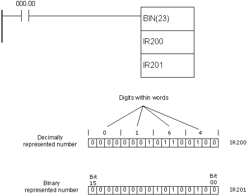
Upon fulfilling the condition on bit
IR000.00, instruction changes the contents of memory location IR200
so that its numerical value remains unchanged; in other words, only
the representation of the location’s contents changes. If the
contents of the location IR200 is “164” decimal, this instruction
would convert it to “0000000010100100”. One of the purposes of this
instruction is preparing the contents of memory location for one of
the binary operations. |
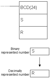
E.61 BINARY TO BCD
- Converts binary number to a decimal number
|
Description |
Instruction converts
binary represented number from the word S to a decimal number in the
word R. Contents of the word S remains unchanged. |
|
Ladder symbol |
 |
|
Limitations |
Word DM6144 - DM6655
cannot be used as operand R. |
|
Flag |
ER flag changes state
to ON in case of error.
EQ flag changes state to ON if the result equals “0”. |
|
Example |
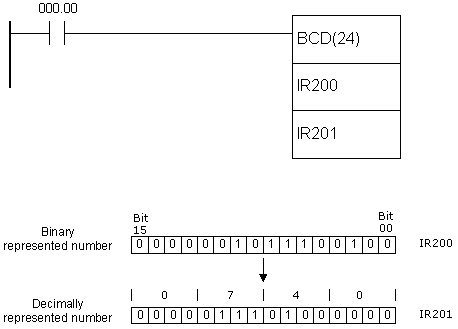
Upon fulfilling the condition on bit
IR000.00, instruction changes the contents of memory location IR200
so that its numerical value remains unchanged; in other words, only
the representation of the location’s contents changes. If the
contents of location IR200 is “000000101100100” binarny, this
instruction would convert it to “740” decimaly. One of the purposes
of this instruction is preparing the contents of memory location for
one of BCD operations. |
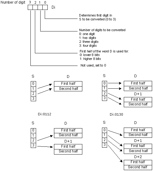
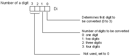
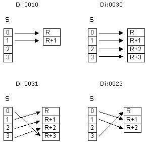
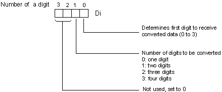
E.62 4 TO 16 DECODER
- 4 to 16 decoder
|
Description |
Instruction converts
up to four 4-bit hexadecimal digits of values from 0 to 15. The
result of the instruction is stored into memory locations from
address R to R+3, depending on how many digits was converted.
Converted digit in the result is represented with a set bit on a
position corresponding to the value of a digit. If the value of a
digit is “C” (12 decimaly) the twelfth bit of the result word will
be set.
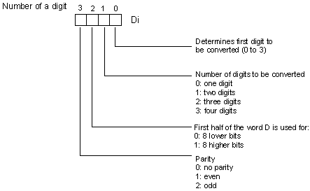
The first digit to be converted, as
well as the number of digits to be converted, is determined in the
control word Di. If the number of digits for conversion is greater
than the number of digits remaining in the word S, then the missing
digits are taken from the starting digit anew. The structure of the
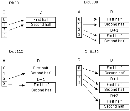
control word Di is shown on the picture below.
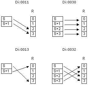
Some of the
combinations of control word values along with their meaning are
given below:
 |
|
Ladder symbol |
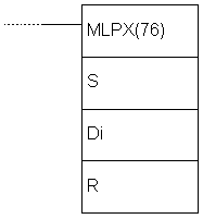 |
|
Limitations |
Two rightmost digits
of the word Di have to be between 0 and 3. Words DM6144 - DM6655
cannot be used as operand R. |
|
Flag |
ER flag changes state
to ON in case that (R + number of digits) exceeds the range of a
given memory block. |
|
Example |
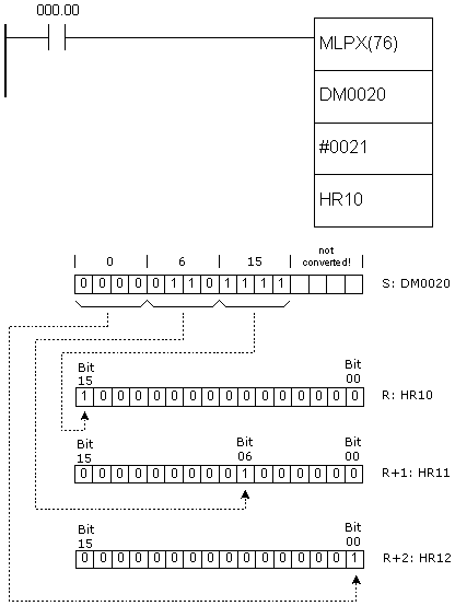
Upon fulfilling the condition on bit
IR000.00, instruction converts three digits from the digit no.1 in
the word DM0020. As there are three digits to be converted, the
result will take three memory locations starting from HR10. Digit 0
in the word DM0020 is not converted. |
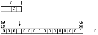
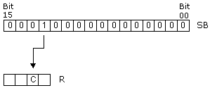
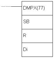
E.63 16 TO 4 ENCODER
- 16 to 4 encoder
|
Description |
Instruction determines
the highest set bit in SB and according to it, stores the 4-bit
hexadecimal value to a certain place in the result word R.
In the example below, bit 12 of the location on address SB is set,
which would be “C” in a hexadecimal representation.
Precise place for
storing the converted value in the word R is determined by a control
word Di. The same word also determines the number of words to be
converted, starting from the address of the word SB. For this
example, the control word would be “0001”.
The first digit to be
converted, as well as the number of digits to be converted, is
determined in the control word Di. If the number of digits for
conversion is greater than the number of digits remaining in the
word S, then the missing digits are taken from the starting digit
anew. The structure of the control word Di is shown on the picture
above.
Some of the
combinations of control word values along with their meaning are
given below:
 |
|
Ladder symbol |
 |
|
Limitations |
Two rightmost digits
of the word Di have to be between 0 and 3. Words DM6144 - DM6655
cannot be used as operands R, SB and Di. |
|
Flag |
ER flag changes state
to ON if (SB + number of digits) exceeds the range of a given memory
block or if the word to be converted equals zero. |
|
Example |
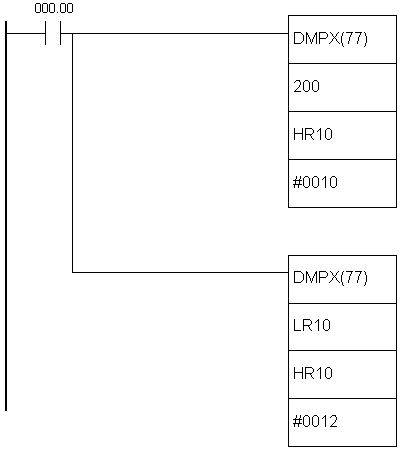
Upon fulfilling the condition on bit
IR000.00, first DMPX instruction converts two words, IR200 and
IR201. The control word is “0010”, meaning that two words are
converted (digit 1) and stored starting from the zero digit in the
result (rightmost digit 0). After the first DMPX instruction, the
second one is executed, converting two words from addresses LR10 and
LR11 and storing them in the result word HR10, starting from the
digit no.2. Therefore, the word HR10 contains four converted words
in the following order: IR200, IR201, LR10, LR11. More detailed
explanation of how the instruction works is given on the following
picture.
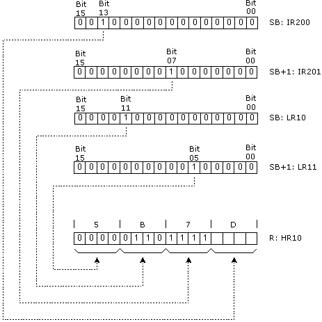
Presuming that binary value is the
one from locations IR200, IR201, LR10 and LR11, as in example, the
result of conversion in the result word HR10 would be “5B7D”. |
E.64 ASCII CONVERT
- Converts to ASCII code
|
Description |
Instruction converts
digits from the word S to their ASCII equivalent and stores the
result in the words starting from the address D. The control word Di
determines the first converted digit, the number of digits to be
converted and which half of the word D contains the first 8-bit
ASCII converted code. IIf the number of digits for conversion is
greater than the number of digits remaining in the word S, then the
missing digits are taken from the starting digit anew from the word
S. Digit with the highest position of the word Di has a role of
parity bit and it can take values between 0 and 2 - not having
parity, parity and non-parity. Parity bit is actually a highest bit
of the 8-bit ASCII code. When the third digit of the word Di equals
zero, this bit is always zero. If the third digit of the word Di
equals one, then this bit represents parity, or simply put, this bit
is set when the number of ones in the other 7 bits of ASCII is odd
making the number of ones even. If the ASCII value equals “31”
(binary “0011 0001”), even parity would change the highest bit to
one, changing the ASCII number to “1011 0001” or “B1”. The status of
parity bit does not affect the interpretation of ASCII code. Odd
parity bit behaves in similar fashion, but with the opposite
function. It’s purpose is to ensure that the number of ones in ASCII
code is always odd. The following picture represents interpreting
the value of word Di and the picture after that gives several
versions of values of the word Di and how they affect the
instruction.
 |
|
Ladder symbol |
 |
|
Limitations |
Two lower digits of
the words Di must have values betweenmoraju imati 0 and 3. Words
DM6144 - DM6655 cannot be used as operand D. |
|
Flag |
ER flag changes state
to ON if two rightmost digits of the word Di do not fall within the
specified range (0-3) or the result word exceeds the boundaries of
memory area. |
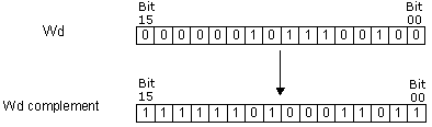
E.65 COMPLEMENT
- Complements a word
|
Description |
Instruction executes
the second complement of the word Wd and stores it into word Wd
again. The second complement means that ones become zeros and vice
versa.
 |
|
Ladder symbol |
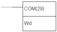 |
|
Limitations |
Words DM6144 - DM6655
cannot be used as operand Wd. |
|
Flag |
ER flag changes state
to ON in case of error.
EQ flag changes state to ON if the result equals zero. |
E.66 LOGICAL AND
- Operation logical "AND" on the contents of a word
|
Description |
Instruction executes
the operation logical “AND” on words I1 and I2. The result of the
operation is stored into word R. Operation logical “AND” puts one in
the result only if the same position of words I1 and I2 also contain
one.
 |
|
Ladder symbol |
 |
|
Limitations |
Words DM 6144 - DM6655
cannot be used as operand R. |
|
Flag |
ER flag changes state
to ON in case of error.
EQ flag changes state to ON if the result equals zero. |
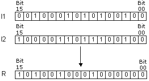
E.67 LOGICAL OR
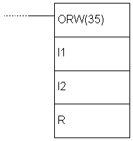
- Operation logical "OR" on the contents of a word
|
Description |
Instruction executes
the operation logical “OR” on words I1 and I2. The result of the
operation is stored into the word R. Operation logical “OR” puts the
one in the result if at least one of the words I1 and I2 contains
one on that position.
 |
|
Ladder symbol |
 |
|
Limitations |
Words DM6144 - DM6655
cannot be used as operand R. |
|
Flag |
ER flag changes state
to ON in case of error.
EQ flag changes state to ON if the result equals zero. |
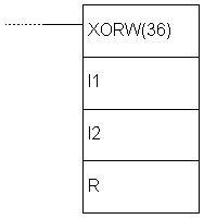
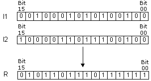
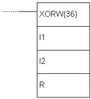
E.68 EXCLUSIVE OR
- Operation "EXCLUSIVE OR" on the contents of a word
|
Description |
Instruction executes
operation “EXCLUSIVE OR” on the words I1 and I2. The result of the
operation is stored into the word R. Operation exlusive “OR” puts
one in the result only if the same position of the words I1 and I2
contains different values.
 |
|
Ladder symbol |
 |
|
Limitations |
Words DM6144 - DM6655
cannot be used as operand R. |
|
Flag |
ER flag changes state
to ON in case of error.
EQ flag changes state to ON if the result equals zero. |
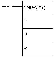
E.69 EXCLUSIVE NOR
- Operation "EXCLUSIVE NOR" on the contents of a word
|
Description |
Instruction executes
operation “EXCLUSIVE OR” on the words I1 and I2. The result of the
operation is stored into the word R. Operation exclusive “NOR” puts
one in the result only if the same position of words I1 and I2
contains the same value, whether it is “0” or”1”.
 |
|
Ladder symbol |
 |
|
Limitations |
Words DM6144 - DM6655
cannot be used as operand R. |
|
Flag |
ER flag changes state
to ON in case of error.
EQ flag changes state to ON if the result equals zero. |
E.70 BIT COUNTER
- Counts the number of ones in a given word
|
Description |
Instruction counts the
number of bits with the state “1” in words from address SB to
SB+(N-1) and puts the result on the address of the word R.
 |
|
Ladder symbol |
 |
|
Limitations |
Words DM6144 - DM6655
cannot be used as operand R. Word N cannot have zero value. |
|
Flag |
ER flag changes state
to ON in case that N isn’t BCD number or in case that SB and
SB+(N-1) don’t belong to the same memory area.
EQ flag changes state to ON if the result equals zero. |
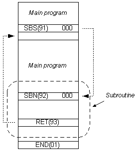
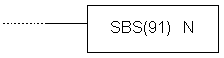
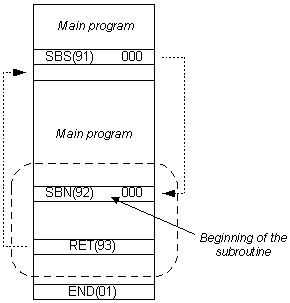
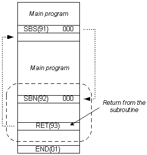
E.71 SUBROUTINE
ENTRY - Enters the subroutine
|
Description |
Instruction changes
the course of the main program towards subroutine, at the
instruction line of the main program which contains the instruction
SBS. Number of instructions N has to be in 000 - 049 range. When the
instruction condition is fulfilled, all the instructions between
SBN(92) and the first RET(92) instruction are executed. Upon
processing the RET instruction, program returns to the line
immediately following the instruction SBS which called the
subroutine in the first place. The same subroutine may be called
from several places in the program.
 |
|
Ladder symbol |
 |
|
Limitations |
Number of subroutine
has to be in 000 - 049 range. |
|
Flag |
ER flag changes state
to ON when non-existing subroutine is called, when the subroutine
calls itself or when the subroutine being executed at the moment is
called. |
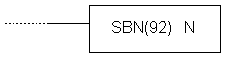
E.72 SUBROUTINE
DEFINE - Beginning of a subroutine
|
Description |
Instruction marks the
beginning of a subroutine. Each subroutine is defined with its
number N. All subroutines have to be placed after the main program
and instruction END has to follow the last RET instruction of the
last subroutine SBN.
 |
|
Ladder symbol |
 |
|
Limitations |
Number of the
subroutine has to be in 000 - 049 range. Each number may be used
only once. |
|
Flag |
It has no effect on
any particular flag. |
E.73 SUBROUTINE
RETURN - Return from a subroutine
|
Description |
Instruction executes
the return from the subroutine to the main program. Each subroutine
must contain the RET instruction. This instruction jas on number of
its own, naturally assuming that it belongs to the previous SBN
instruction.
 |
|
Ladder symbol |
 |
|
Limitations |
Number of the
subroutine has to be in 000 - 049 range. Each number may be used
only once. |
|
Flag |
It has no effect on
any particular flag. |
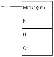
E.74 MACRO -
Macro
|
Description |
Instruction MCRO
enables one subroutine to substitiute several subroutines having the
same structure, but different operands. Instruction has 4 input
words SR232 to SR235 and 4 output words SR236 to SR239 used for
sending or receiving the subroutine parameters. Upon fulfilling the
condition, the instruction copies the contents of locations I1 - I3
to words SR232 - SR235. Upon execution of subroutine N, values of
the words SR236 - SR239 are copied to words O1 - O3. |
|
Ladder symbol |
 |
|
Limitations |
Number of the
subroutine has to be in 000 - 049 range. Each number may be used
only once. |
|
Flag |
ER flag changes state
to ON when non-existing subroutine is called, when the subroutine
calls itself or when the subroutine, being
executed at the moment, is called. |
|
Example |
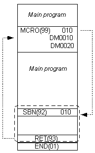
Instruction MCRO calls the
subroutine with the number 010. Contents of words DM0010 - DM0013 is
copied to SR232 - SR235 and upon execution of the instruction,
contents of words SR236 - SR239 is copied to the words DM0020 -
DM0023. |
E.75 INTERRUPT
CONTROL - Interrupt control
|
Description |
Instruction controls
the interrupts and executes one of the seven functions presented in
the table below, according to the value of the word C1.
|
C1 |
Function |
|
000 |
Mask/unmask interrupts |
|
001 |
Clear the interrupt input |
|
002 |
Read the current mask for
interrupt inputs |
|
003 |
Reset decrement counter
and unmask interrupts |
|
004 |
Reset increment counter
and unmask interrupts |
|
100 |
Mask all interrupts |
|
200 |
Unmask all interrupts |
NOTE: Value of the word C1 004
refers to models CPM2A/CPM2C of PLC controller, so it will not be
detailed here.
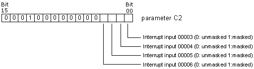
C1=000
Function is used for masking and unmasking the interrupt inputs
00003 - 00006. Masked interrupts are registered, but the part of the
program assigned to them will not be executed until the mask is off.
Upon unmasking interrupt input, interrupt routine will immediately
take place (unless, in the meantime the bit corresponding to that
interrupt input is reset with the instruction INT, parameter
C1=001). The input being masked or unmasked is determined by
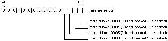
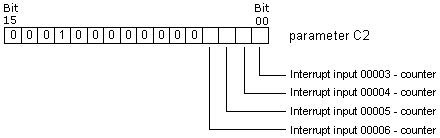
parameter C2 according to the following scheme (bear in mind that we
work with bits and not with digits of the word C2). Bits 4, 5,
6...15 should be set to zero. All interrupt inputs are masked upon
starting the PLC controller.
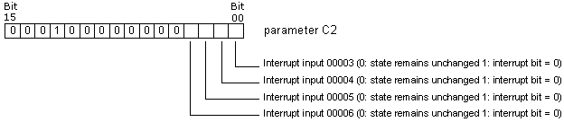
C1=001
Function resets the registered interrupts, so that interrupt routine
cannot take place upon unmasking the interrupt input. Bits 4, 5,
6...15 of the word C2 should be set to zero.
C1=002
Function reads the status of the mask for interrupt inputs 00003 -
00006 and stores the read state into the word C2. Interrupt input is
masked if the state of the corresponding bit equals “1”. Bits 00 -
03 correspond to interrupt inputs 00003 - 00006.
C1=003
Function restarts the interrupt inputs in the counter mode. The
current counter value (SR240 - SR243) is set to the starting state
and the interrupt is unmasked. If C1=003, decremental counter is
restarted, while in the case of C1=004 incremental counter is
restarted. As CPM1A model of PLC does not feature incremental
counter, this option should not be used. When using the options
C1=003 or C1=004 differencial form of the instruction shoud be used
@INT or else the current counter state (PV) will be reset to the
starting state (SV) and the interrupt will never be generated.
Writing the value “0000” to the starting counter state and executing
the INT instruction with parameter C1=003 stops the counter and
disables interrupts.
To start the counter
again, non-zero value should be written to a starting value SV and
the instruction INT executed. Interrupts in the counter mode can be
masked by executing the instruction INT with parameter C1=000 and
set corresponding bit in C2. If same is done, but with “0” for the
appropriate position in the word C2 interrupt input will behave as a
regular interrupt ulaz and not as counter interrupt input.
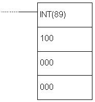
C1=100
Function masks all the interrupts including the interval timer
interrupts and the high-speed counter interrupts. Masked interrupts
are registered, but are not executed. This function is also called a
global interrupt mask and it does not affect the masks of specific
interrupts. This option should be used for temporary disabling all
the interrupts. It is cmmonly used in pair, one function masks all
the interrupts and the other one unmasks them. Function cannot be
used within the interrupt routine.
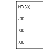
C1=200
Function unmasks all the interrupts including the interval timer
interrupts and the high-speed counter interrupts. If the specific
interrupt is masked, global unmasking does not affect the state of
the specific interrupt input state. Function cannot be used within
the interrupt routine.
 |
|
Ladder symbol |
 |
|
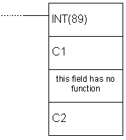
Flag |
ER flag changes state
to ON if:
C1 is not 000, 001, 002, 003, 004, 100 or 200.
C2 is not in 0000 - 000F range.
INT instruction is executed with C1=100 or 200 within the interrupt
routine.
INT instruction is executed with C1=100 when all inputs are already
masked.
INT instruction is executed with C1=200 when all inputs are already
unmasked. |
E.76 INTERVAL TIMER
- Interval timer
|
Description |
Instruction is used
for controling the timer interrupt. Instruction mode is determined
according to the value of the word C1.
|
C1 |
Function |
|
000 |
Start the interrupt timer
with only one timer |
|
003 |
Start the timer with
periodical interrupts |
|
006 |
Read the current timer
value |
|
010 |
Stop the timer |
C1=001 or 003
C2 can be either a constant or an address of a word in PLC
controller memory.
C2=constant
If C2 is a constant, then it represents the starting value of
decremental counter in BCD format (form 0000 to 9999 which is
equivalent to 0 - 9.999 ms) and C3 represents the number of the
interrupt routine (from 000 to 049).
C2=address of a word in memory
If C2 is a word in PLC controller memory, then its contents is a
starting value of decremental counter in BCD format. Cotents of the
word C2+1 represents the measurement unit (BCD, 0005 - 0320) in 0.1s
decrements. Interval is, in that case, 0.5 - 32ms. Starting value of
the timer is calculated as C2 * (C2+1) * 0.1s. C3 represents the
number of the interrupt routine.
C1=006
Function reads the current timer state. Parameter C2 represents the
memory address where the read timer state is stored, while C2+1
stores the measurement unit. Parameter C3 reresents the memory
address where the data concerning the time passed since the last
decrementation of timer in BCD format is stored in 0.1s units.
C1=010
Function stops the timer. Parameters C2 and C3 are without function
and should be set to “0000”. |
|
Ladder symbol |
 |
|
Flag |
ER flag changes state
to ON if C1 is not 000, 003, 006 or 010 or in case that the number
of interrupt routine is not within 0000 - 0049 range. |
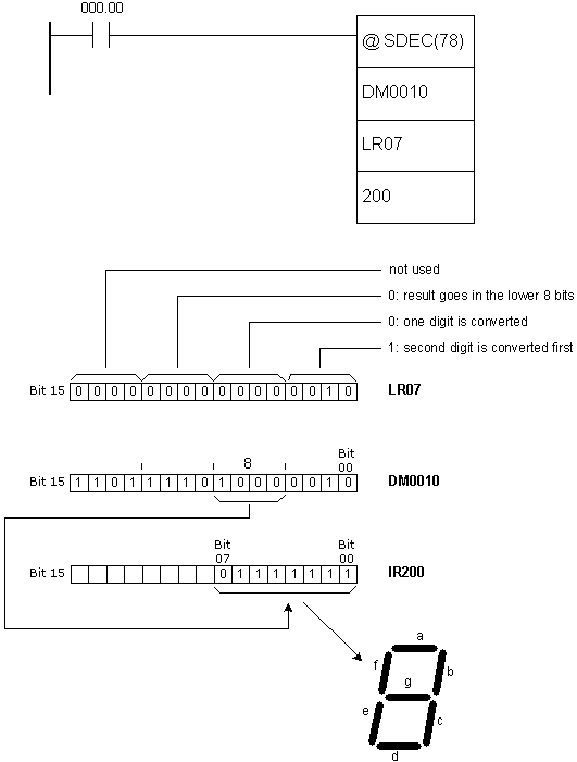
E.77 7-SEGMENT
DECODER - Seven-segment decoder
E.78 I/O REFRESH
- Premature writing to I/O table
|
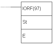
Description |
Instruction checks the
states of words from the address St to the address E and refreshes
them according to the current state of the program. Instruction is
used when we want to know the state of certain bit without waiting
it to be refreshed in the course of regular cycle of refreshing the
inputs and outputs of PLC controller (IR000 - IR019). |
|
Ladder symbol |
 |
|
Limitations |
Address of the word St
has to be lower or equal to the address of the word E. |
|
Flag |
ER flag changes state
to ON if words St and E do not belong to IR000 - IR019 range or in
case that the address of the word St is greater than the address of
the word E. |
E.79 MESSAGE
- Displays message in the programming console
|
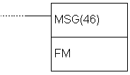
Description |
Instruction reads the
contents of eight words from the address FM and displays them in the
program console. Contents of the word has to be in ASCII format,
with every word containing 2 ASCII characters. If not all the words
are to be displayed in the console, displaying can be stopped if the
string “OD” is put into following word. |
|
Ladder symbol |
 |
|
Limitations |
Words DM6144 - DM6655
cannot be used as operand FM. |
|
Flag |
ER flag changes state
to ON in case of error. |
E.80 MODE CONTROL
- Controls the high-speed counter or the pulse output
|
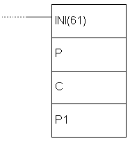
Description |
Instruction controls
the high-speed counter. There are several functions depending on
parameters P, C and P1. Parameter P defines if
either high-speed counter or pulse output will be controlled with
this instruction.
|
P |
Function |
|
000 |
Designates the input of PLC
controller that will be used as high-speed counter (000.00,
000.01 and 000.02). Determines mono-phase signal of logical
zero with no acceleration/deceleration (outputs 010.00 and
010.01)
Determines mono-phase signal of
logical zero with trapezoid acceleration/deceleration (output
010.00) |
|
010* |
Determines mono-phase signal "1"
with no acceleration/deceleration (output 010.01) |
|
100* |
Designates interrupt input 0 in
counter mode (input 000.03) |
|
101* |
Designates interrupt input 1 in
counter mode (input 000.04) |
|
102* |
Designates interrupt input 2 in
counter mode (input 000.05) |
|
103* |
Designates interrupt input 3 in
counter mode (input 000.06) |
NOTE: * refers to CPM2A/CPM2C PLC
controller models.
|
C |
P1 |
Function |
|
000 |
000 |
Starts comparing the current
value with the values from comparison table (CTBL) |
|
001 |
000 |
Stops comparing the current
value with the values from comparison table (CTBL) |
|
002 |
New value of the current state
(PV) |
Changes the current value PV of
high-speed counter or interrupt input in counter mode |
|
003 |
000 |
Stops the pulse output |
|
005* |
New value of the current state
(PV) |
Changes the current state of
pulse output |
|
006* |
000 |
Stops the synchronized pulse
output |
NOTE: * refers to CPM2A/CPM2C PLC
controller models.
C=000 or
C=001
Function starts or stops comparing the current value of high-speed
counter PV with the values from the comparison table created with
instruction CTBL. If the comparison table wasn’t created ahead of
executing the INI instruction, the error occurs. Generally, when INI
instruction with C=000 is used, differential form @INI is
recommended, because one set of starting comparisons is sufficient.
C=002
Function changes value of the current state of the high-speed
counter or the interrupt in the counter mode.
Fast counter PV ( P=0 )
Function changes the contents of PV to 8-digit BCD number contained
in the words P1 and P1+1. If differential-phase mode or ”up/down “
input mode is used, PV can have value between F838 8608 and 0838
8607, where “F” as the first digit is treated as a minus sign. PV
can have value between 000 0000 and 1677 7215 in incremental mode.
Interrupt counter input PV ( P=100, P=101, P=102, P=103)
Function changes the contents of PV to 4-digit hexadecimal number
from the word P1 (from 0000 to FFFF).
C=003
Function stops the pulse output.
C=004
Function changes the value of the current PV pulse output state to
an 8-digit BCD value in the words P1 and P1+1. Change cannot be done
while the pulse output is in function. New value can be from
-16.777.215 to +16.777.215. Bit no.15 of the word P1+1 behaves like
a sign: “0” stands for positive, “1” stands for negative number.
C=003
Function stops the synchronized pulse output. |
|
Ladder symbol |
 |
|
Limitations |
If CPM1 or CPM1A PLC
controller is used, parameter P has to be 000 and parameter C has to
be 000, 001, 002 or 003. P1 has to be 000 if C is not 002 or 004. If
an address from DM memory area is used as parameter P1, reading and
writing to that location has to be enabled. |
|
Flag |
ER flag changes state
to ON if comparison table exceeds one memory area. |
E.81 HIGH-SPEED
COUNTER PV READ - Reads the current value of high-speed counter
|
Description |
Instruction controls the current state of high-speed counter, pulse
output, interrupt input in counter mode or input frequency for
synchronized input. There are several functions depending on
parameters P, C and D.
Parameter P defines if either high-speed counter or pulse output
will be controlled with this instruction.
|
P |
Function |
|
000 |
Designates the input of PLC
controller that will be used as high-speed counter (inputs
000.00, 000.01 and 000.02). Designates input frequency for
synchronized pulse input (inputs 000.00, 000.01 and 000.02).
Determines mono-phase signal of logical zero with no
acceleration/deceleration (outputs 010.00 and 010.01)
Determines
mono-phase signal of logical zero with trapezoid
acceleration/deceleration (output 010.00) |
|
010* |
Determines mono-phase signal "1"
with no acceleration/deceleration (output 010.01) |
|
100* |
Designates interrupt input 0 in
counter mode (input 000.03) |
|
101* |
Designates interrupt input 1 in
counter mode (input 000.04) |
|
102* |
Designates interrupt input 2 in
counter mode (input 000.05) |
|
103* |
Designates interrupt input 3 in
counter mode (input 000.06) |
NOTE: * refers to CPM2A/CPM2C PLC
controller models.
Control word determines the type of
data to be accessed.
|
C |
Destination word |
Function |
|
000 |
D
and D+1 |
Reads the
current state of high-speed counter, of interrupt input in
counter mode or input frequency of synchronized pulse control |
|
001 |
D |
Reads the status of high-speed counter or pulse output |
|
002 |
D |
Reads the results of comparing with values from comparison
table |
|
003 |
D
and D+1 |
Reads the current value of pulse output |
NOTE: * refers to CPM2A/CPM2C PLC
controller models.
C=000
Function reads the current value of PV of the specified high-speed
counter or the interrupt input in counter mode.
Fast counter PV or input frequency (P=000)
When the output is used as the high-speed counter, instruction reads
the current value of the specified fast counter and writes an
8-digit BCD value to D and D+1.
If differential-phase mode or ”up/down “ input mode is used, PV can
have value between F838 8608 and 0838 8607, where “F” as the first
digit is treated as a minus sign. PV can have value between 000 0000
and 1677 7215 in incremental mode. When the input is used as
synchronic pulse input, the instruction reads the input frequency
and writes an 8-digit BCD value to D and D+1. Range of the input
frequency is 0000 0000 - 0002 0000.
Interrupt counter input PV ( P=100, P=101, P=102, P=103)
Function changes the contents of PV to 4-digit hexadecimal number
from the word D (from 0000 to FFFF).
C=001
Function reads the status of the high-speed counter or the pulse
input and stores the data into D.
Status of the high-speed counter or the pulse input 0 (P=000)
The table below shows the function of bits in the word D when P=000.
Bits not mentioned are not used and are always zero.
|
For... |
Bit |
Function |
|
High-speed counter |
00 |
Status of comparing high-speed counter with values from
comparison table (0: not
compared, 1:compared) |
| 01 |
High-speed counter below/above the specified value
(0: in range, 1:out of
range) |
|
Pulse output |
05 |
Total number of pulses defined for pulse output 0
(0: number of pulses not
defined, 1:number of pulses defined) |
| 06 |
Defined number of pulses on output 0 executed
(0: not executed,
1:executed) |
| 07 |
Pulse output 0 state (0:
stopped, 1:executing) |
| 08 |
Current state PV of pulse output
(0: in range, 1:out of
range) |
| 09 |
Rate on pulse output 0
(0: constant, 1:accelerates/decelerates) |
Status of the pulse output 1
(P=010)
The table below shows the function of bits in the word D when P=010.
Bits not mentioned are not used and are always zero.
|
Bit |
Function |
|
05 |
Total number of pulses defined for pulse output 1
(0: number of pulses not
defined, 1:number of pulses defined) |
|
06 |
Defined number of pulses on output 1 executed (0:
not executed, 1:executed) |
|
07 |
Pulse output 1 state (0:
stopped, 1:executing) |
|
08 |
Current state PV of pulse output
(0: in range, 1:out of
range) |
|
09 |
Rate on pulse output 1
(0: constant, 1:accelerates/decelerates) |
C=002
Function reads the result of comparing the current value PV with 8
areas defined by instruction CTBL and stores data into D. Bits 0 to
7 contain the results of comparing with 8 ranges from the comparison
table (0: not in range, 1: in range).
C=003
Function reads the value of current state of PV pulse output and
stores it to 8-digit BCD value in words D and D+1. PV can have value
from -16.777.215 to +16.777.215. Bit no.15 of the word D+1 behaves
like a sign: “0” stands for positive, “1” stands for negative
number. |
|
Ladder symbol |
 |
|
Limitations |
If CPM1 or
CPM1A PLC controller is used, parameter D has to be 000 and
parameter C has to be 000, 001 or 002. If an address from DM memory
area is used as parameter D, reading and writing to that location
has to be enabled.
D and D+1 have to belong to the same memory area. |
|
Flag |
ER flag
changes state to ON if an error concerning the value of instruction
operand occurred. |
E.82 COMPARISON
TABLE LOAD - Defines a comparison table
|
Description |
Instruction forms the
comparison table for working with high-speed counter. Depending on
parameter C, comparison can be immediate or it can be called upon
with instruction INI.
|
C |
Function |
|
000 |
Registers comparison table containing values and starts
comparing |
|
001 |
Registers comparison table containing ranges and starts
comparing |
|
002 |
Registers comparison table containing values. Comparing starts
with INI instruction |
|
003 |
Registers comparison table containing ranges. Comparing starts
with INI instruction |
When the current value of PV
matches some of the specified table values or it belongs to one of
the specified ranges, the appropriate subroutine is called. If the
high-speed counter is not enabled in PC area (DM6642) instruction
CTBL cannot be executed.
Comparing with values
Comparison table can have up to 16 values. Each of these values is
assigned a number of subroutine that is called when the current
value matches the table value. With CPM1 and CPM1A models,
comparison is done one at a time in each cycle, while with models
CPM2A and CPM2C comparison is done for all table values
simultaneously. After comparing with the last table value,
comparison starts from the first value again. The table below shows
the structure of the comparison table containing values.
Each value is assigned three words in the table. If the value “FFFF”
is used as the number of subroutine, no subroutine will be executed
in case of a match.
|
TB |
Number of values that current value is compared with (0001 to
0016, BCD) |
|
TB+1 |
Value no.1 (lower four digits in BCD format) |
|
TB+2 |
Value no.1 (higher four digits in BCD format) |
|
TB+3 |
Number of subroutine for matching the first value |
|
... |
|
Comparing with a range of values
Comparison table with ranges contains 8 ranges, which the current
value PV is compared with. Ranges can overlap, allowing that the
current value PV falls into several of these; in this case, the
subroutine of the first matching area is called. If the value “FFFF”
is used as the number of subroutine, no subroutine will be executed
in case of a match.
|
TB |
Lower value no.1 (lower four
digits in BCD format) |
|
TB+1 |
Lower value no.1 (higher four
digits in BCD format) |
|
TB+2 |
Higher value no.1 (lower four
digits in BCD format) |
|
TB+3 |
Higher value no.1 (higher four
digits in BCD format) |
|
TB+4 |
Number of subroutine in case
that the current value PV is within range no.1 |
|
... |
|
|
TB+35 |
Lower value no.8 (lower four
digits in BCD format) |
|
TB+36 |
Lower value no.8 (higher four
digits in BCD format) |
|
TB+37 |
Higher value no.8 (lower four
digits in BCD format) |
|
TB+38 |
Higher value no.8 (higher four
digits in BCD format) |
|
TB+39 |
Number of subroutine in case
that the current value PV is within range no.8 |
|
|
Ladder symbol |
 |
|
Limitations |
In each area lower
border has to be lower than the upper border. Number of subroutine
can be used for several ranges.
Table has to belong to a single memory area. Parameter D has to be
000 and the parameter C has to be 000, 001, 002 or 003. |
|
Flag |
ER flag changes state
to ON if an error concerning the value of instruction operand
occurred. |
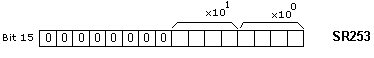
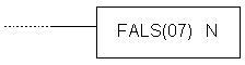
E.83 FAILURE ALARM
AND RESET - Generates error code
|
Description |
Instruction generates
the code of an error that took place, so that the programmer can use
that information for debugging or program maintenance. Error code is
stored in the first 8 bits of the word SR253 and has value between
01 and 99.
In case of multiple errors, only
one code will be displayed. To display the other codes, it is
necessary to reset bits 00-07 of the word SR253 via instruction FAL
with parameter N=00. Upon each reset, new error code will be
displayed (if there is more than one error). Error code remains in
PLC controller memory after the power is off. When error occurs,
besides the code, programmer will be notified with blinking diode on
the casing of PLC controller.
Instruction FAL with parameter N=0
may be used for resetting the message created with the instruction
MSG. |
|
Ladder symbol |
 |
E.84 SEVERE FAILURE
ALARM - Generates fatal error code
|
Description |
Instruction generates
the code of an error that took place, so that the programmer can use
that information for debugging or program maintenance. Error code is
stored in the first 8 bits of the word SR253 and has value between
01 and 99. Upon occurence of fatal error, diode ALARM/ERROR turns on
on the casing of PLC controller and the PLC stops operating.
PLC controller continues the
program execution only when cause of error is removed. Error code
remains written and may be read. |
|
Ladder symbol |
 |
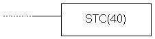
E.85 SET CARRY
- Sets carry bit
|
Description |
Instruction changes
the state of carry bit CY to ON. Carry bit is an integral part of
the word SR255, and its address is SR255.04. |
|
Ladder symbol |
 |
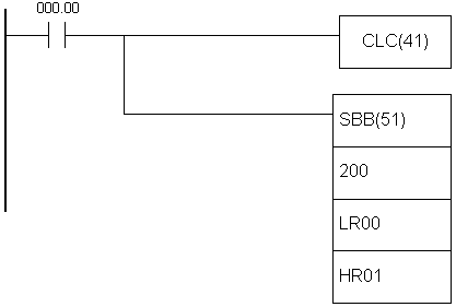
E.86 CLEAR CARRY
- Resets carry bit
|
Description |
Instruction changes
state of carry bit CY to OFF. Carry bit is an integral part of the
word SR255, and its address is SR255.04. |
|
Ladder symbol |
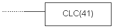 |
|